S R Latch Truth Table
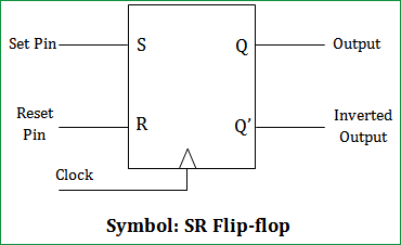
A bistable multivibrator has two stable states, as indicated by the prefix bi in its name. Typically, one state is referred to as set and the other as reset. The simplest bistable device, therefore, is known as a set-reset, or S-R, latch. SR flip flop is the simplest type of flip flops. SR Flip Flop Construction, Logic Circuit Diagram, Logic Symbol, Truth Table, Characteristic Equation & Excitation Table are discussed.
The S-R Latch block is an abstracted behavioral model of a set-reset latch. It does not model the internal individual MOSFET devices (see Assumptions and Limitations for details). Therefore, the block runs quickly during simulation but retains the correct I/O behavior.
View all of my You Tube Videos
Also visit and subscribe to My YouTube Channel
- Characteristics table for SR Nand flip-flop Characteristics table is determined by the truth table of any circuit, it basically takes Q n, S and R as its inputs and Q n+1 as output. Q n+1 represents the next state while Q n represents the present state. While dealing with the characteristics table, the clock is high for all cases i.e CLK=1.
- The truth table for an SR Flip Flip (i.e. SR Latch) has been shown in the table below. You can learn more about SR flip flops and other logic gates by checking out our full list of logic gates questions. About Electrical4U Electrical4U is dedicated to the teaching and sharing of all things related to electrical and electronics engineering.
Back to Hobby Electronics What to Know
Here we will learn to build a SR latch from NAND gates. Then we will use that to build a D flip-flop.
A SR latch is a form of a bistable multivibrator. It has two stable states, as indicated by the prefix bi in its name. Typically, one state is referred to as set and the other as reset. The simplest bistable device, therefore, is known as a set-reset, or S-R, latch. To create an S-R latch, we can wire two NAND (or NOR) gates in such a way that the output of one feeds back to the input of another, and vice versa.
Here I will address the NAND gate version.
The Q and not-Q outputs are supposed to be in opposite states. But both forms of SR latches have illegal input states. For a NAND gate latch both inputs LOW turns ON both output LEDs.


Having both S and R equal to 0 is called an invalid or illegal state for the S-R Latch. Otherwise, making S=1 and R=0 'sets' the multivibrator so that Q LED is ON and !Q LED is OFF Conversely, making R HIGH and S LOW 'resets' the latch in the opposite state. When S and R NAND latch inputs are both equal to 1, the outputs 'latch' in their prior states.
This is opposite for a NOR gate based SR Latch. Both input HIGH turns both LEDs OFF. See Basic NOR Gate SR Latch Circuit.
Ref. Wiki
Normally the inputs are left at HIGH, but are normal LOW in the NOR gate version. This created differing input electrical connections.

Here we use two NAND to create a clocked SR Latch. With a 74LS00 the 4 NAND gates allow a single component to be used to create the gated latch. In the NOR gate version we had to use a separate 74LS08 integrated circuit.
Note the truth table. With S and R both HIGH the NAND gates convert this to LOW at A and B. That is still an illegal condition.
Above we added an inverter between S and R. This prevents S and R from both being HIGH or LOW. This forms a D flip-flop. Note the following table:
Note the change happens when CLK goes LOW to HIGH then LOW. The state of Q and !Q at the H-L transition is stored.

Finally if built from NAND or NOR gates the final D flip-flop is identical.
Images used in this series:
General Electronics Learning and Projects
- H-Bridge Motor Control with Power MOSFETS Updated
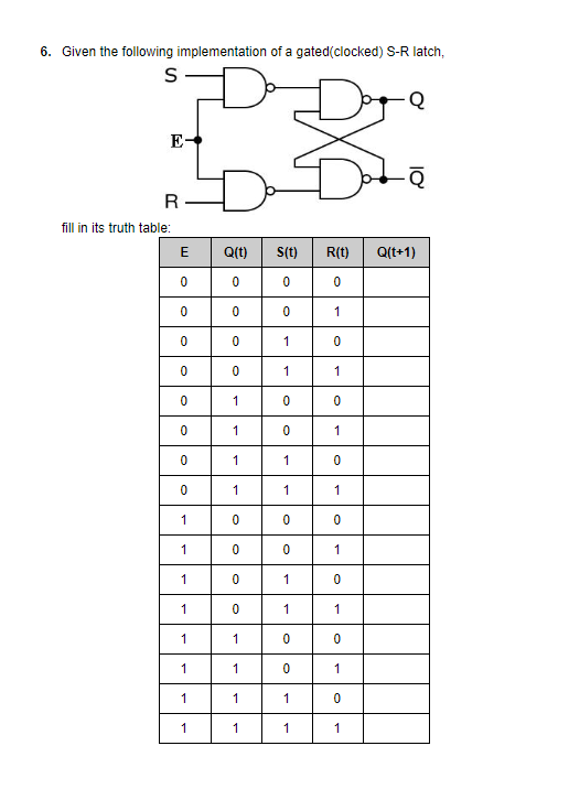
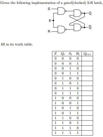
It is sometimes useful in logic circuits to have a multivibrator which changes state only when certain conditions are met, regardless of its S and R input states.
The conditional input is called the enable, and is symbolized by the letter E. Study the following example to see how this works:
Gated SR- Latch Truth Table
When the E=0, the outputs of the two AND gates are forced to 0, regardless of the states of either S or R. Consequently, the circuit behaves as though S and R were both 0, latching the Q and not-Q outputs in their last states.
Only when the enable input is activated (1) will the latch respond to the S and R inputs. Note the identical function in ladder logic:
Gated S-R Latch Ladder Logic
A practical application of this might be the same motor control circuit (with two normally-open push button switches for start and stop), except with the addition of a master lockout input (E) that disables both push buttons from having control over the motor when its low (0).
Sr Latch Table
Once again, these multivibrator circuits are available as prepackaged semiconductor devices, and are symbolized as such:
S-R Gated Latch Symbol
It is also common to see the enable input designated by the letters “EN” instead of just “E.”
REVIEW:
- The enable input on a multivibrator must be activated for either S or R inputs to have any effect on the output state.
- This enable input is sometimes labeled “E”, and other times as “EN”.
Sr Flip Flop
RELATED WORKSHEETS:
